Most people who sit down to use an oscilloscope for the first time end up staring at a glowing green line like it's a foreign language. Honestly, that's not your fault — the manual that came with the scope is either a thousand pages of engineering jargon or a single diagram that assumes you already know what you're doing. That's why a well-designed reading oscilloscope worksheet is the only thing standing between you and total frustration. It turns that intimidating waveform into something you can actually decode.
Look — if you're troubleshooting a circuit right now or trying to pass an electronics exam next week, you don't have time to learn the entire history of cathode-ray tubes. You need to know which knob adjusts the time base, what that voltage division number actually means, and why your signal looks like a squiggly mess instead of a clean sine wave. The truth is, most tutorials skip the real-world gotchas — like ground loops or probe compensation — that will wreck your readings before you even start.
By the time you finish working through a structured worksheet — the kind that makes you trace waveforms and measure rise times with your own hands — you'll stop guessing and start seeing the story the scope is telling you. No more freezing up when someone asks for peak-to-peak voltage. You'll actually know what you're looking at. And here's the thing: that confidence changes everything when you're debugging a board that's smoking.
Spending hours staring at a waveform on a cheap LCD screen is a rite of passage for anyone learning electronics. But here's the hard truth: most tutorials skip the practical grunt work. They explain theory beautifully, then leave you stranded when you actually need to probe a noisy signal. The real skill isn't reading a perfect sine wave from a textbook — it's interpreting the messy, jittery, real-world garbage your probe picks up. That's where a structured approach, like working through a reading oscilloscope worksheet, forces you to stop guessing and start measuring with intent.
Why Your First Waveform Will Lie to You
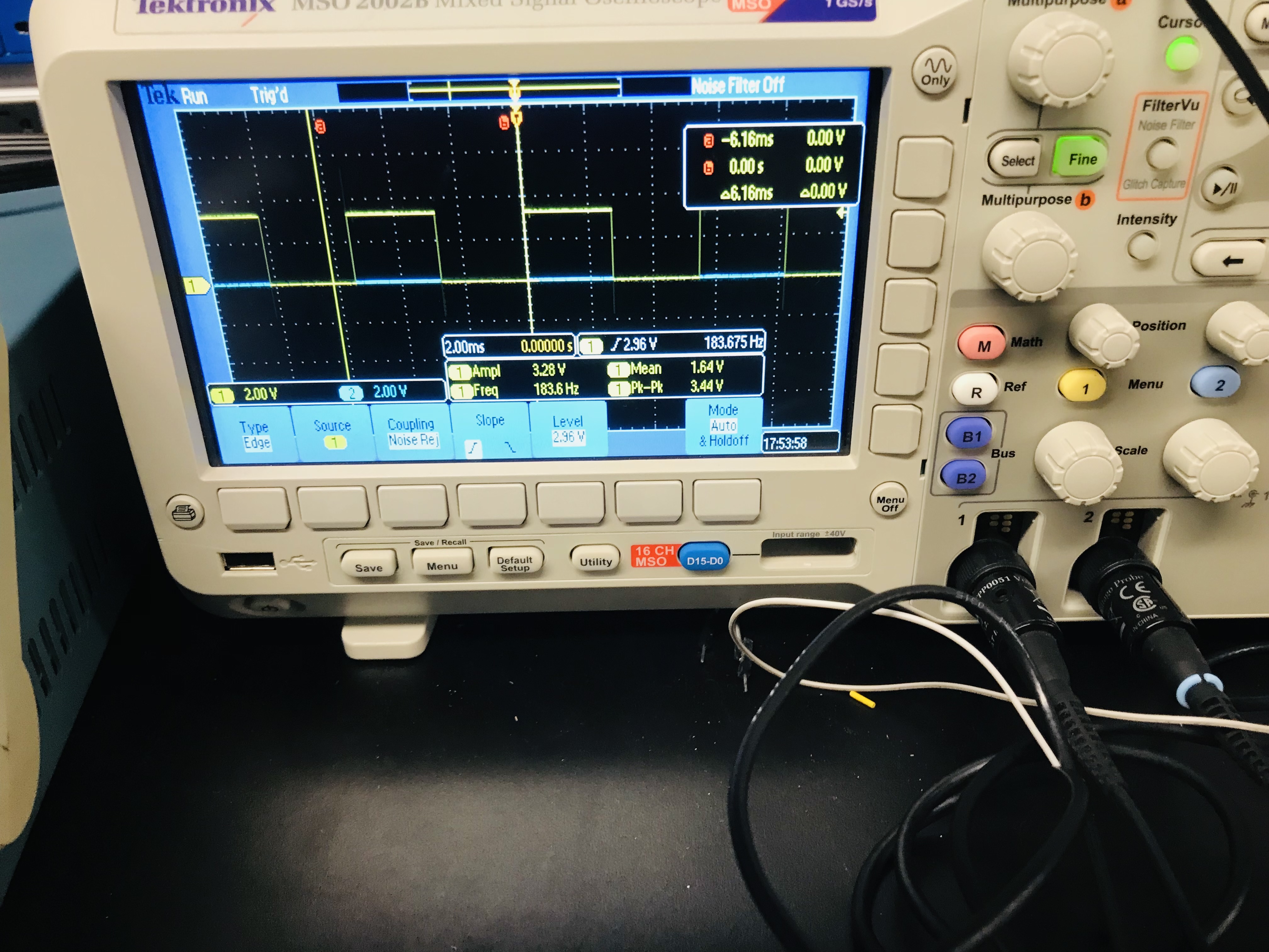
Every beginner makes the same mistake. They connect the probe, see a squiggly line, and assume it's correct. It almost never is. The biggest lie is the trigger setting. If your trigger level is set too high or too low, the waveform will drift, flicker, or appear as a solid blur. Most people fiddle with the timebase knob hoping for a miracle. Stop doing that. Instead, always set your vertical scale first before touching the horizontal controls. You need to know the voltage range of your signal to even see it properly. A typical worksheet exercise will have you probe a 5V peak-to-peak square wave, but if your volts/div is set to 10V, you'll see a flat line and think your circuit is dead. That's not a theory problem. That's a technique problem.
Here's what nobody tells you: your probe's compensation adjustment is more important than the oscilloscope's calibration. Most 10x probes have a small trimpot near the BNC connector. If you don't square that off against the scope's built-in 1kHz reference signal, your readings will be off by 10-20% at higher frequencies. I've seen seasoned technicians chase phantom noise for an hour only to find an uncompensated probe. A good worksheet will make you perform this compensation check as the very first step. It feels tedious. It saves your sanity.
Decoding the Grid: Timebase and Volts/Div Working Together
The graticule on your screen isn't just decoration. Each major division represents a specific time and voltage value. The trick is learning to read both axes simultaneously without getting cross-eyed. When you're looking at a 1kHz sine wave, each cycle takes 1 millisecond. If your timebase is set to 200µs/div, you'll see exactly five divisions per cycle. That's a clean, predictable measurement. But change the timebase to 1ms/div, and now you're cramming one full cycle into a single division. You lose detail. This is where a worksheet forces you to calculate before you twist the knob. You learn to estimate: "I need to see three full cycles, so my sweep speed should be roughly 300µs/div." That mental math becomes automatic after a dozen exercises.
Triggering: The Hidden Hand That Stops the Blur
Most people treat the trigger section like a mystery box. They flip it to "Auto" and hope for the best. That works for steady signals, but it fails completely on glitches or burst data. The real skill is using normal trigger mode with an edge slope selection. If you're looking at a rising edge of a digital pulse, set your slope to rising and your trigger level to roughly 50% of the signal amplitude. The waveform locks into place like a photograph. A good worksheet will have you trigger on a falling edge specifically to prove a point — you'll see the signal invert horizontally, which is a massive clue for debugging logic timing issues. Nobody tells you that the trigger holdoff control is your best friend when dealing with complex pulse trains. It prevents the scope from re-triggering on the same pulse, letting you see the actual pattern.
Measuring Real Signals vs. Idealized Ones
The gap between textbook waveforms and real signals is where experience lives. A clean 5V square wave from a function generator is easy. Now probe the output of a 555 timer running on a breadboard with long jumper wires. You'll see overshoot, ringing, and maybe a 200mV ripple on the flat top. A worksheet that gives you ideal values and then asks you to measure actual values is worth its weight in gold. For example, you might be told the signal should be 3.3V peak-to-peak, but your measurement shows 3.7V. That extra 0.4V is real information — it points to impedance mismatch or a weak pull-up resistor. A structured worksheet teaches you to trust the measurement, not the expectation.
| Parameter | Ideal Value (Worksheet) | Real-World Measurement | Probable Cause |
|---|---|---|---|
| Peak-to-Peak Voltage | 5.0V | 5.4V | Uncompensated 10x probe |
| Rise Time (10%-90%) | 10ns | 18ns | Excessive probe capacitance |
| Frequency | 1.000kHz | 1.023kHz | Oscillator drift or loading |
| Overshoot | 0% | 12% | Poor ground lead connection |
The table above shows exactly the kind of discrepancy a reading oscilloscope worksheet should make you hunt for. Each row is a diagnostic rabbit hole. When you see that 12% overshoot, you don't just write it down — you shorten your ground lead to the absolute minimum length, and suddenly the overshoot drops to 3%. That's the difference between reading a manual and actually learning. The worksheet is a map, but the probe is your shovel. Dig into every anomaly. If you treat the exercise like a checklist, you'll miss the point. If you treat it like a detective game, you'll internalize skills that transfer to every circuit you'll ever troubleshoot.
One Last Thing Before You Go
You’ve just walked through the process of interpreting waveforms, setting timebases, and decoding the story your circuit is trying to tell you. But here’s what I want you to sit with for a moment: every time you hit that Auto Set button without thinking, you’re outsourcing your curiosity. The real growth happens when you slow down, touch each control, and ask why the trace looks the way it does. That habit doesn’t just make you better at using an oscilloscope — it rewires how you troubleshoot everything. It turns guesswork into grounded confidence. Whether you’re debugging a power supply at 2 AM or teaching a junior engineer, the ability to read a screen with clarity is the difference between spinning your wheels and actually fixing the problem.
I know what you might be thinking: “This is great, but I’ll forget half of it by next week.” That’s normal. Nobody remembers every setting or probe compensation trick after reading once. The goal isn’t perfection — it’s having a mental map so that next time you’re staring at a glitch, you know where to look. Trust the process. You don’t need to be an expert today; you just need to be one step more informed than you were yesterday. That’s how mastery builds — quietly, stubbornly, one waveform at a time.
Here’s where you can make this stick: bookmark this page right now, or better yet, share it with someone who’s just getting started with test gear. If you want to go deeper, browse our gallery of annotated signal examples — seeing real-world captures next to clean theory makes everything click faster. And if you haven’t already, grab a copy of the reading oscilloscope worksheet we linked earlier. It’s not homework — it’s your cheat code for the next time you’re probing a noisy rail or a glitchy clock line. Print it, keep it near your bench, and use it until the steps become muscle memory. The only bad move is not starting.